MODULE
CONTROL
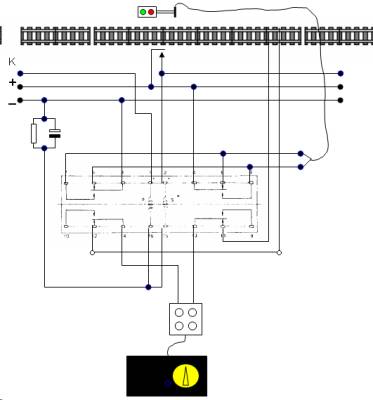
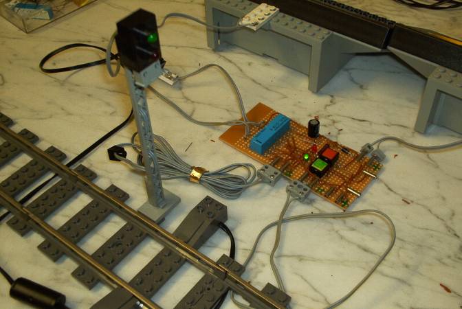
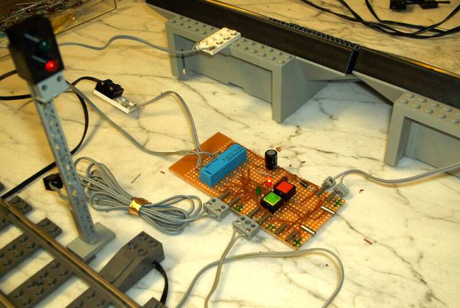
 Function of the Module Control System:
Additional components
are:
(2)
push buttons for manual control
(2) LEDs (1x red, 1x green ) to indicate status
(1) diode to protect relay
connectors
(1) diode to prevent loop signals
All parts were
purchased from an internet electronic parts retailer (Conrad) and
absolute standard items. For more information > see my email
address on the homepage > home)
Schematic
set-up:
Working
system:
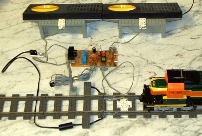
HP
1
HP 0
 ...
...
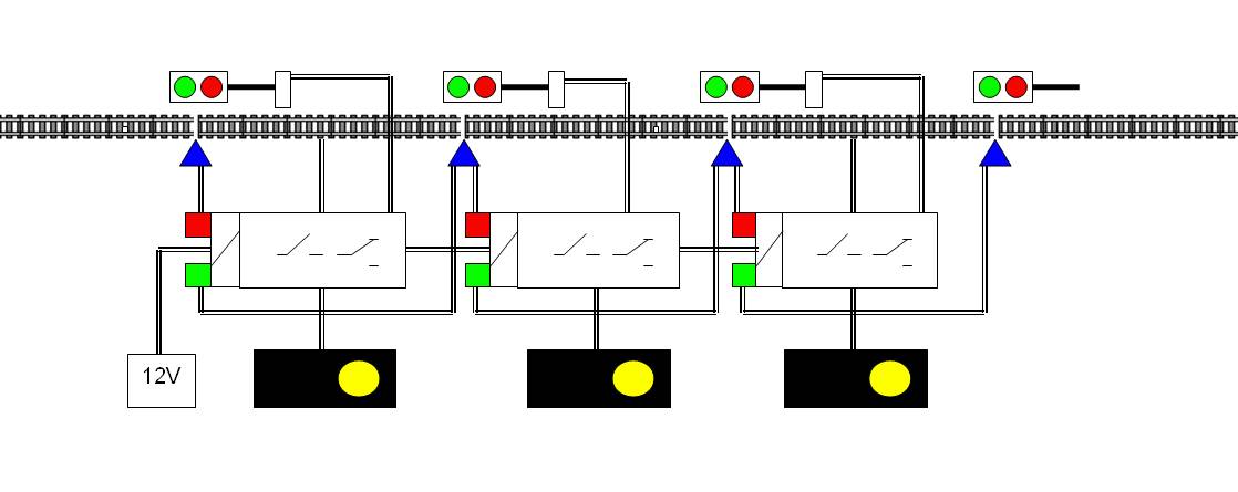
The
Sensor:
The
sensor (Reed-contact) reacts on all magnets, e.g. on
LEGO-couplings and motors. That makes the system simple and all LEGO
trains can run on this layout. No special contactors at the trains are
required. The problem at the moment is that all trains need to be
equally long to avoid contact failures, - I am busy solving this!
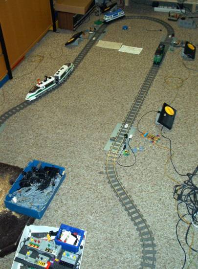
Testrun with 5 modules and 3 trains:
home